Author: Shandong Lunan Machine Tool Co., Ltd. Wang Shao deposit Cheng Xiantong
Zaozhuang Daxing Mining Co., Ltd. Zhang Haixia
The boring method is a high-precision, high-efficiency, economical and practical method for processing the box hole system. It is widely used in actual production. Each company also designs and manufactures different special boring machine tools according to its actual situation. The model plane introduced this time is used for the lifting and sliding seat processing of our company's G62 milling machine. The author discusses the new ideas, new technologies and new techniques adopted in the design and manufacture.
1. Equipment characteristics and structure
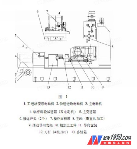
The equipment is a combined die plane (see Figure 1), which can process horizontal and vertical hole systems in one clamping, which improves production efficiency; semi-automatic operation is realized. After processing the horizontal hole system, just press With the fast forward button, it will automatically turn to the vertical hole processing position, repeating the positioning accuracy within 0.01mm; the cost-effective optimization design of the transmission system and components, the stepless speed regulation of the work feed; the biggest highlight of the device is The lower cost realizes the application of the handwheel electronic pulse generator on ordinary electrical control (non-CNC).
2. System design
(1) Die design According to the structural characteristics of the machined parts, the process and structure analysis are carried out to determine the optimal process plan, including the positioning structure, clamping structure, set of tool holder tools and multi-axle box design. Wait. Fig. 2 is a schematic structural view of a workpiece to be processed.
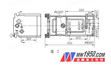
From the structural analysis of the machined parts, the positioning is based on the reference A and B; the machining overhang of the II, III, IV hole system is relatively small, the layout of the die is selected as "single-sided rear guide", and the guide bracket 11 is arranged behind the cutter, the knife The rod 12 is rigidly coupled with the multi-axle box 13 in the form of a Morse cone; the I-axis has a long distance between the two holes, and the end hole has a closed surface, and the die arrangement form selects the "guided combination of the fixed and the suspension", that is, close The guide bracket 11 of the multi-axle box is in a fixed manner, the movable guide bracket 9 is in a movable manner, and the connection between the cutter bar and the multi-axle box is a floating connection. The movable guide bracket 9 enters and exits through the workpiece process hole 265 mm × 415 mm. This die structure contributes to the compactness of the overall structure of the machine tool.
In order to ensure the accuracy of the die and reduce the difficulty of assembly, the I-axis two guide bracket holes are simultaneously processed in the manufacturing process, and the remaining guide bracket holes are roughed and reserved. After assembling the multi-axle box, install the appropriate tool and find the I-axis of the die. The rest of the die-supporting holes are made by the machine itself. Practice has proved to be completely feasible.
(2) The design of the work feed transmission system is shown in Figure 3, including one fast feed motor 1 for rapid movement; one for industrial feed frequency variable motor 2, for work feed (stepless speed regulation) and Micro feed; there is an electromagnetic clutch 3 in the worm and worm gear reducer for quick feed and work feed conversion; the reducer is connected to the lead screw to drive the slide to move.

When moving quickly to the vertical hole machining position, the two proximity switches 6 (see Figure 1) are positioned to stop. When the first proximity switch acts, the fast-forward motor stops, and at the same time delays properly, the electromagnetic clutch is switched, and the rapid feed motor 1 is connected. By setting a reasonable slow speed, the second proximity switch is approached to complete the positioning.
The purpose of setting two proximity switches is to eliminate the large positioning error caused by the inertia in fast movement, and adopt the method of fast and slow first to facilitate accurate positioning; the delay is to protect the damage caused by the rapid conversion of electromagnetic clutch. Through detection, this control method repeats the positioning accuracy within 0.01mm.
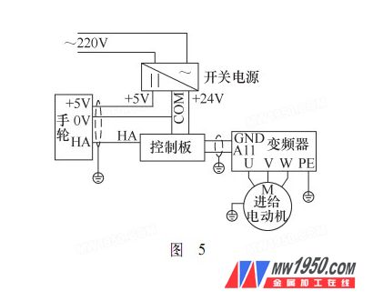
(3) Application design of handwheel electronic pulse generator In order to facilitate the more accurate tool setting and blind hole boring, change the form of the manual hand drive screw and minimize the labor intensity, we designed and made the hand pulse signal. The circuit control board, which is converted into an analog voltage, realizes the micro-feeding function of the electronic handwheel on a special machine for ordinary electric control at a very low cost.
Working principle: The control board is provided with +24V voltage, the VI point is the pulse signal input point (provided by the manual pulse signal generator), and then the pulse signal is converted into 0~ through the conversion circuit composed of components such as module LM337. 10V analog voltage.
The speed of the handwheel rotation causes the output analog voltage to vary from 0 to 10V. The analog voltage controls the rotation speed of the feed variable frequency motor through the frequency converter, so that the speed of the axial running speed changes with the speed of the hand cranking speed, and the operation of the micro-feeding is very conveniently realized.

The change of the feed direction is controlled by the X-axis/Y-axis of the axial selection switch of the handwheel electronic pulse generator, which are respectively connected in series to the interlock control circuit of the feed direction by selecting the X-axis or the Y-axis. Change the advance or retreat in the feed.
The principle of the circuit control board is shown in Figure 4. The basic connection principle is shown in Figure 5.
3. Conclusion
After the special machine is put into use, the machining accuracy of the workpiece completely meets the design requirements, and the efficiency is greatly improved; the handwheel electronic pulse generator is well used and has been patented, which can be applied to the upgrade of ordinary machine tools; repeated positioning of double proximity switches Accuracy and control methods can be extended to the use of other special machine tools; it provides a new design idea for the design of our special machine tools in the future.
Led Panel Light,Led Panel,Panel Light,Light Panels
Jiangmen hengshenghui Lighting Co., Ltd , https://www.jmsunbright.com