1. Overview
The lower ring is made of martensitic stainless steel (ZG00Cr13Ni4Mo), primarily used in hydropower stations for structural protection and support. Due to the high-performance requirements, advanced casting and heat treatment processes are essential. The casting has a relatively thin wall, with an average thickness of approximately 106 mm, which makes it challenging to fill and solidify properly during the casting process. This often results in small shrinkage cavities and porosity in the central area, significantly affecting the mechanical strength of the component. Moreover, the material is difficult to repair, and any welding can lead to a hardened microstructure, increasing the risk of post-weld cracking. Our company successfully cast the lower ring using a specialized casting method. However, after machining and ultrasonic testing, some defects were still found to be above acceptable limits. To address this, we implemented a tailored repair welding process that effectively addressed the over-standard defects. Figures 1 and 2 show the 3D illustration and physical image of the lower ring, respectively.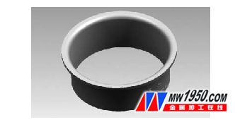
Figure 1: 3D Illustration of the Lower Ring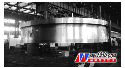
Figure 2: Physical Image of the Lower Ring
2. Repair Welding Process and Operation
Since the casting was produced without any machining allowance, excessive heat during repair welding could cause deformation or cracking. To prevent this, our welding team developed a precise and controlled repair welding procedure: 1. Local preheating temperature was maintained between 70–110°C. 2. The interpass temperature was strictly controlled at 80–160°C. 3. Electrodes were dried at 350°C for 1.5 hours and then stored in a thermos bucket to maintain dryness. 4. Special attention was given to ensuring proper fusion between the weld and the base metal, particularly avoiding slag inclusion at the root and joint. 5. A single-layer, multi-pass welding technique was used, with no swinging motion. Each layer of weld was kept under 6 mm to minimize residual stress. 6. Welding parameters included a φ4mm electrode, with a current range of 150–170A and a short arc technique. 7. After each pass, the weld was gently hammered to relieve stress. 8. The interlayer temperature was strictly maintained at 80–160°C to avoid excessive stress and distortion caused by rapid or continuous welding. 9. Care was taken to ensure proper fusion along the groove edges, preventing issues like incomplete penetration or slag inclusion. 10. If poor fusion or cracking was detected during the process, the welding was immediately stopped, the area cleaned, and re-welded using a grinding wheel or head as needed. After welding, the part was wrapped in asbestos felt to cool slowly. Photographs of the repair welding process are shown in Figures 3 and 4.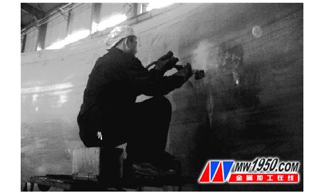
Figure 3: Welder Using Wind Target for Stress Relief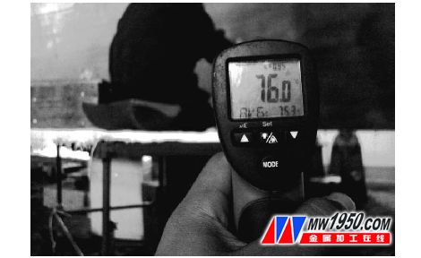
Figure 4: Repair Welding Temperature Approximately 76°C
For more detailed information, please refer to the attached documents.
Floating Sphere,Brass Solid Sphere,Cpvc Solid Sphere,Stainless Steel Solid Sphere
Antong Valve Co.,Ltd , https://www.atvalveball.com